How a Plasma Cutter Works
What is plasma?
To properly explain how a plasma cutter works, we must begin by answering the basic question “What is plasma? In its simplest terms, plasma is the fourth state of matter. We commonly think of matter having three states: a solid, a liquid, and a gas. Matter changes from one state to the other through the introduction of energy, such as heat. For example, water will change from a solid (ice) to its liquid state when a certain amount of heat is applied. If the heat levels are increased, it will change again from a liquid to a gas (steam). Now, if the heat levels increase again, the gases that make up the steam will become ionized and electrically conductive, becoming plasma. A plasma cutter will use this electrically conductive gas to transfer energy from a power supply to any conductive material, resulting in a cleaner, faster cutting process than with oxyfuel.
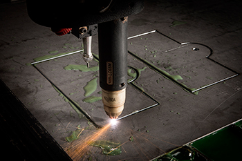
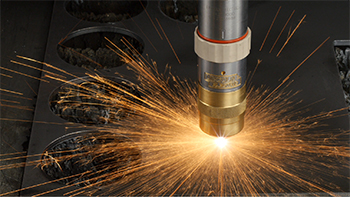
The plasma arc formation begins when a gas such as oxygen, nitrogen, argon, or even shop air is forced through a small nozzle orifice inside the torch. An electric arc generated from the external power supply is then introduced to this high pressured gas flow, resulting in what is commonly referred to as a “plasma jet”. The plasma jet immediately reaches temperatures up to 40,000° F, quickly piercing through the work piece and blowing away the molten material.
Plasma system components
- Power supply -- The plasma power supply converts single or three phase AC line voltage into a smooth, constant DC voltage ranging from 200 to 400VDC. This DC voltage is responsible for maintaining the plasma arc throughout the cut. It also regulates the current output required based on the material type and thickness being processed.
- Arc Starting Console – The ASC circuit produces an AC voltage of approximately 5,000 VAC at 2 MHz which produces the spark inside of the plasma torch to create the plasma arc.
- Plasma torch – The function of the plasma torch is to provide proper alignment and cooling of the consumables. The main consumable parts required for plasma arc generation are the electrode, swirl ring, and nozzle. An additional shielding cap may be used to further improve cut quality, and all the parts are held together by inner and outer retaining caps.
The vast majority of plasma cutting systems today can be grouped into either conventional or precision categories.

Conventional plasma systems typically use shop air as the plasma gas, and the shape of the plasma arc is basically defined by the orifice of the nozzle. The approximate amperage of this type of plasma arc is 12-20K amps per square inch. All handheld systems utilize conventional plasma, and it is still used in some mechanized applications where the part tolerances are more forgiving.

Precision plasma systems (high current density) are designed and engineered to produce the sharpest, highest quality cuts that are achievable with plasma. The torch and consumable designs are more complex, and additional pieces are included to further constrict and shape the arc. A precision plasma arc is approximately 40-50K amps per square inch. Multiple gases such as oxygen, high purity air, nitrogen, and a hydrogen/argon/nitrogen mixture are used as the plasma gas for optimum results on a multitude of conductive materials.

Handheld Operation
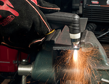
In a typical handheld plasma system, such as our Tomahawk® Air Plasma, the electrode and nozzle consumable parts are in contact with one another inside the torch when in the OFF state. When the trigger is squeezed, the power supply produces a DC current that flows through this connection, and also initiates the plasma gas flow. Once the plasma gas (compressed air) builds up enough pressure, the electrode and nozzle are forced apart, which causes an electrical spark that converts the air into a plasma jet. The DC current flow then switches from electrode to nozzle, to a path between the electrode and work piece. This current and airflow continues until the trigger is released.

Precision plasma operation
Inside a precision plasma torch, the electrode and nozzle do not touch, but are isolated from one another by a swirl ring which has small vent holes that transform the preflow/plasma gas into a swirling vortex. When a start command is issued to the power supply, it generates up to 400VDC of open circuit voltage and initiates the preflow gas through a hose lead set to the torch. The nozzle is temporarily connected to the positive potential of the power supply through a pilot arc circuit, and the electrode is at a negative.

Next, a high frequency spark is generated from the Arc Starting Console which causes the plasma gas to become ionized and electrically conductive, resulting in a current path from electrode to nozzle, and a pilot arc of plasma is created.

Once the pilot arc makes contact to the work piece (which is connected to earth ground through the slats of the cutting table), the current path shifts from electrode to work piece, and the high frequency turns off and the pilot arc circuit is opened.

The power supply then ramps up the DC current to the cutting amperage selected by the operator and replaces the preflow gas with the optimum plasma gas for the material being cut. A secondary shielding gas is also used which flows outside of the nozzle through a shield cap.

The shape of the shield cap and the diameter of its orifice forces the shield gas to further constrict the plasma arc, resulting in a cleaner cut with very low bevel angles and smaller kerf.
