Fixture and Platform Calibration
The fixture calibration procedure helps ensure that the cameras are always reading the exact location of the fixture platform. It is necessary to go through the fixture calibration procedure in three different situations:
- When the system is first installed
- If the user is seeing consistent erroneous data that relates to position such as proximity. If the output values seem to be incorrect, the fixture may
need to be recalibrated. - Every 30 days
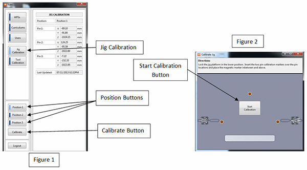
With the fixture platform clamped in place, press the “Jig Calibration” button on the left side of the screen. Now, press the corresponding “Position” button. (Figure 1)
- Repeat the above calibration steps for all fixture platform positions
-
Once the correct position button is selected, pres the “Calibrate” button on the bottom of the screen. This will bring up the Calibrate Jig window. (Figure 2)
-
This window has directions that show where to place the LED markers.
-
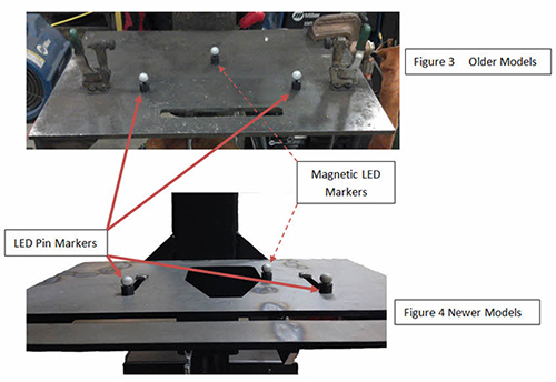
Two of the markers need to be placed over the 2 pin locations on the platform, and the 3rd marker is magnetic and should be placed in between and above the other two markers (towards the back of the jig platform but no more than halfway back). (Figure 3 and 4)
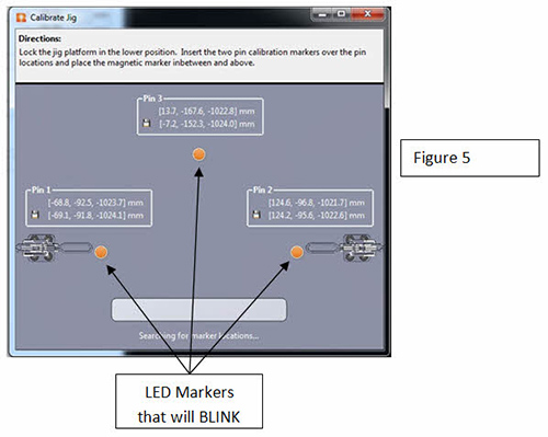
- Once the markers are in place, press the “Start Calibration” button on the screen (Figure 2). The LED markers on the screen will start to blink while various numbers appear above them (Figure 5). During this time, the equipment is determining the position of the fixture platform.
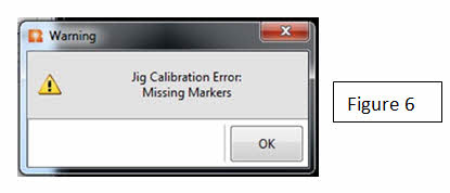
- In some cases, there might be an error with the calibration due to the markers not being within the field of view or if there is a bright light in the area. In those cases an error might pop up as shown in Figure 6.
- If this happens, press the “OK” button, verify that the markers are placed properly and that there aren’t any sources of bright light in the area, and repeat the calibration steps.
- Once the calibration is complete, the Calibrate Jig window will automatically close. The Jig Calibration menu will still be displayed and the numerical values for Pins 1-3 will be updated. The date and time of the calibration will also be updated and displayed. (Figure 7)


